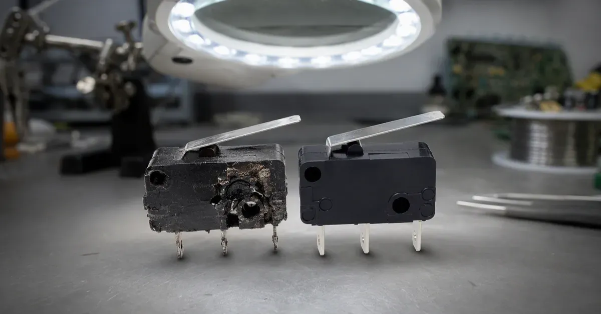
Micro Switch Failure Modes: Causes & Prevention
17 August 2026 | NY Circuit Team
Micro switches can be reliable components, but a mismatch in selection or installation can still cause field failures. Here are commonly reported failure modes and practical ways to reduce the risk.
1. Contact Welding
What happens: The contacts weld together under high inrush current, and the switch never opens again.
Why: The switch rating was chosen for steady-state current, but the actual load has a large inrush — motors, solenoids, capacitors and lamp loads can draw 5-10× the running current at switch-on.
Prevention:
- Check the inrush rating in the data sheet, not just the nominal rating
- Add an inrush limiter (NTC) or relay for heavy loads
- Choose a switch with higher contact rating or wider contact gap
2. Lever / Actuator Fatigue
What happens: The lever breaks or the actuation point drifts after weeks of operation.
Why: Operating the switch beyond its rated travel or force — usually because the actuator geometry was approximated instead of designed.
Prevention:
- Respect the maximum permissible travel and force from the drawing
- Use a roller lever for cam/slide applications (rolling contact instead of scraping)
- Choose stainless levers for high-cycle applications
3. Seal Failure on “Waterproof” Switches
What happens: A supposedly waterproof switch fails from moisture ingress.
Why: The switch itself is IP67, but the connector or cable entry is not — or the switch is mounted in a position where water pools.
Prevention:
- Use pre-wired sealed versions; every connector is a leak point
- Mount with drainage in mind — never with the actuator as a water cup
- Verify the temperature range; extreme cold embrittles seals
4. Terminal Fatigue and Wiring Damage
What happens: Intermittent operation from cracked solder joints or broken quick-connect terminals.
Why: Vibration plus rigid wiring concentrates stress at the terminal.
Prevention:
- Use PCB pins with through-hole soldering for vibration environments
- Provide strain relief / service loop in the harness
- Avoid soldering heat damage: 3 seconds max at 350°C
5. Wrong Operating Point for the Application
What happens: The switch trips too early or too late, causing machine faults.
Why: The movement differential (hysteresis) was not matched to the mechanical tolerance of the actuator system.
Prevention:
- Define your acceptable operating position tolerance first
- Choose a switch with a smaller differential for precision detection
- Validate with samples on the real mechanism before tooling
The 10-Minute Reliability Checklist
- Rating at actual inrush (not just nominal)
- Actuator type and travel within limits
- Sealing level matched to environment (IP67 + cable if wet)
- Terminals suited to vibration and assembly
- Differential matched to mechanism tolerance
- Samples tested on the real mechanism
Send us your application details and current part number if you want us to compare the available ZHJ series. Final selection should be checked against the exact data sheet and application conditions. Request a model review